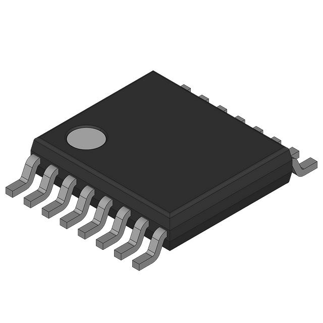
MAX4581EUE
Manufacturer No:
MAX4581EUE
Manufacturer:
Description:
IC SWITCH SP8TX1 80OHM 16TSSOP
Datasheet:
Delivery:


Payment:


In Stock : 0
Please send RFQ , we will respond immediately.


MAX4581EUE Specifications
-
TypeParameter
-
Supplier Device Package16-TSSOP
-
Package / Case16-TSSOP (0.173", 4.40mm Width)
-
Mounting TypeSurface Mount
-
Operating Temperature-40°C ~ 85°C (TA)
-
Crosstalk-78dB @ 1MHz
-
Current - Leakage (IS(off)) (Max)1nA
-
Channel Capacitance (CS(off), CD(off))4pF, 18pF
-
Charge Injection0.5pC
-
-3db Bandwidth-
-
Switch Time (Ton, Toff) (Max)200ns, 100ns
-
Voltage - Supply, Dual (V±)±2V ~ 6V
-
Voltage - Supply, Single (V+)2V ~ 12V
-
Channel-to-Channel Matching (ΔRon)1Ohm
-
On-State Resistance (Max)80Ohm
-
Number of Circuits1
-
Multiplexer/Demultiplexer Circuit8:1
-
Switch CircuitSP8T - Open/Closed
-
PackagingBulk
-
Product StatusActive
-
SeriesAutomotive, AEC-Q100
The 74VHCT138ATTR is a specific model of integrated circuit chip. Here are some of its advantages and potential application scenarios:Advantages: 1. Versatile functionality: The 74VHCT138ATTR is a 3-to-8 line decoder/demultiplexer IC chip. It can decode three binary inputs into eight separate output lines. This versatility enables it to be used in various applications where decoding and demultiplexing are required. 2. High speed: The "VHCT" in the model number stands for Very High-Speed CMOS Technology, indicating that this chip has a high-performance ability to process signals quickly. 3. Low power consumption: The "T" in the model number indicates that this chip is compatible with TTL (Transistor-Transistor Logic) input voltages. It operates on low power supply voltage and consumes less power compared to some other types of IC chips.Application Scenarios: 1. Address decoding: The 74VHCT138ATTR can be used in memory systems or address decoding circuits where it is necessary to decode input addresses into multiple output lines to enable different memory or peripheral devices. 2. Data demultiplexing: It can be used to route specific data signals to different destinations based on input control signals. For example, in communication systems, it can be utilized to demultiplex data streams to different channels. 3. Digital circuit design: The chip can be used as a building block in various digital circuit designs, where demultiplexing functionality is required. It provides a compact and efficient solution for implementing complex digital designs. 4. System control: It can be used to control various devices and modules based on input signals. By properly configuring the input and output lines, it can be utilized in a wide range of systems requiring signal routing or device selection.Keep in mind that the specific application scenarios may depend on the requirements and specifications of the circuit or system being designed. It is always recommended to consult the datasheet and technical documentation of the chip for detailed information and recommended usage guidelines.
MAX4581EUE Relevant information
-
DG509AAZ/883B
Analog Devices Inc./Maxim Integrated -
TS12A4514PE4
Analog Devices Inc. -
TS3A24159DGSR
Analog Devices Inc. -
TS12A4515DBVR
Analog Devices Inc. -
SW202NBC
NXP Semiconductors -
MAX464CNI
NXP Semiconductors -
MC74HC4051ADWR2G
NXP Semiconductors -
74LVC1G3157GWXL
Nexperia USA Inc. -
SW202NBC
NXP Semiconductors -
TDA3683J/N2S,112
Analog Devices Inc.


